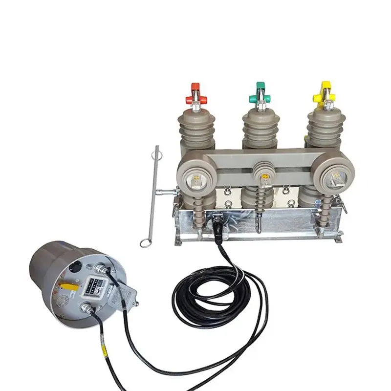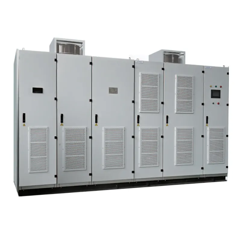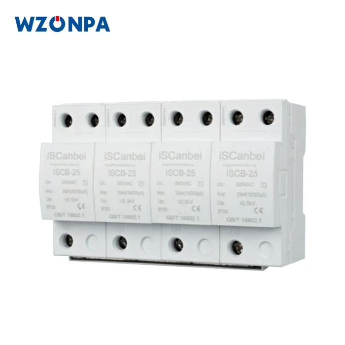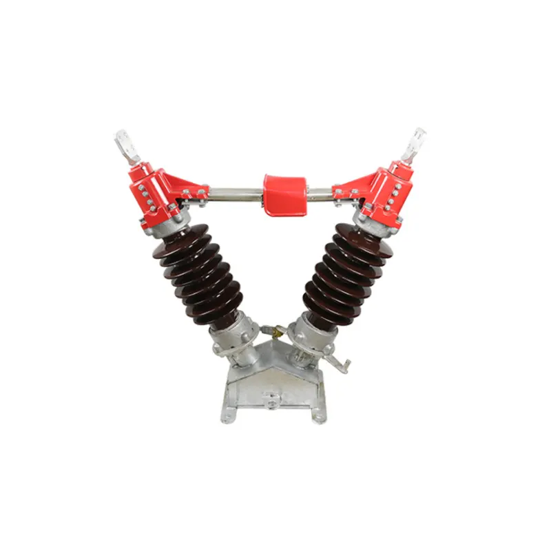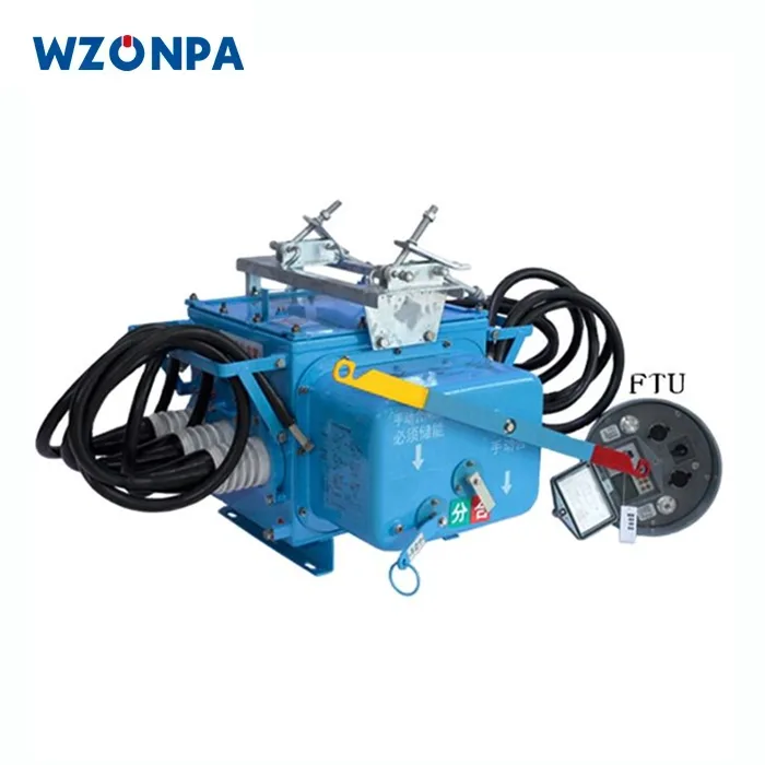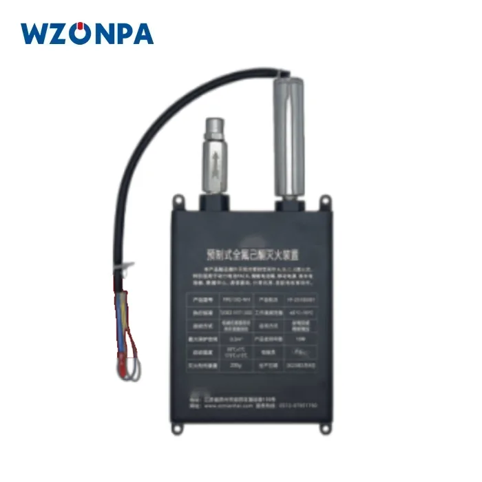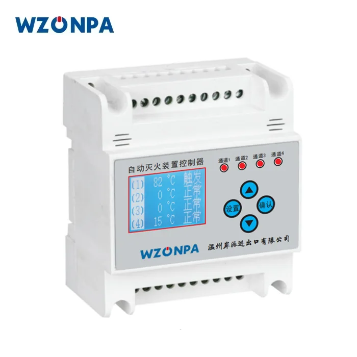

MV Switchgear is a critical part of medium-voltage electrical infrastructure because it provides a controlled point for switching, protection, isolation, monitoring, and distribution. Modern systems may combine circuit breakers, disconnectors, earthing switches, current transformers, voltage transformers, surge protection, busbars, protection relays, and intelligent monitoring within one coordinated assembly. The correct configuration depends on rated voltage, current, short-circuit conditions, installation environment, required maintenance method, feeder arrangement, protection philosophy, and applicable standards. Different technologies, including withdrawable metal-clad systems, ring main units, gas-insulated designs, solid-insulated equipment, and gas-free configurations, address different project conditions. Understanding the relationship between these components is essential for specifying a safe and reliable medium-voltage distribution system.
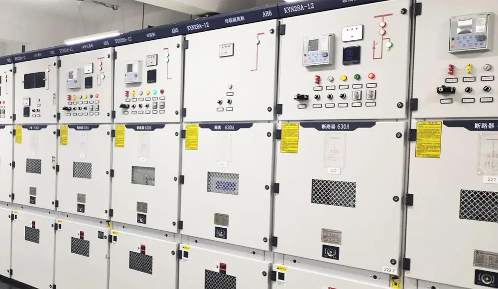
Table of Contents
Click any topic to jump directly to the section.
- 1. What Role Does Medium-Voltage Switchgear Play?
- 2. How Is a Medium-Voltage Switchgear Assembly Structured?
- 3. Which Main Types Are Used in Modern Distribution Systems?
- 4. How Do Rated Voltage and Current Affect Selection?
- 5. Why Are Circuit Breakers, Disconnectors, and Earthing Switches Important?
- 6. How Do Protection and Monitoring Improve System Safety?
- 7. What Is the Difference Between Air, Gas, and Solid Insulation?
- 8. When Is a Withdrawable Design Useful?
- 9. How Should Environmental Conditions Influence the Design?
- 10. How Does MV Switchgear Support Different Applications?
- 11. What Common Selection Mistakes Should Be Avoided?
- 12. How Should Testing and Compliance Be Evaluated?
- 13. What Should a Professional Technical Specification Include?
- 14. Frequently Asked Questions
What Role Does Medium-Voltage Switchgear Play?
Medium-voltage distribution systems must do more than move electrical power from one point to another. They also need controlled switching, fault protection, isolation, measurement, and a defined method for safely operating and maintaining energized equipment.
That is the fundamental purpose of switchgear. In a medium-voltage network, the equipment forms a controlled interface between incoming electrical supply, transformers, outgoing feeders, motors, generators, renewable-energy sources, and downstream distribution equipment.
The system provides a physical and electrical location where circuits can be connected, interrupted, separated, grounded, and monitored according to the operating requirements of the installation.
The importance becomes clear during abnormal conditions. A fault on one feeder should not necessarily require the entire distribution system to be disconnected. Protection devices can identify an abnormal condition and initiate the appropriate switching operation. Isolation devices can then provide a visible or controlled separation for maintenance, depending on the equipment architecture and operating procedure.
Allows operators or automated systems to connect and disconnect circuits according to defined operating conditions.
Works with protection relays and sensing devices to interrupt fault currents and limit damage to the wider network.
Provides a controlled method for separating equipment from energized circuits during maintenance procedures.
Supports voltage, current, protection, monitoring, and control functions through appropriate instrument transformers and sensors.
The system should therefore be viewed as a coordinated assembly rather than a metal enclosure containing a few switches. Busbars, breakers, disconnectors, earthing switches, transformers, relays, interlocks, cables, control circuits, and protection equipment must function together.
For this reason, selecting a switchgear system requires more information than the nominal voltage alone. Rated current, fault level, installation environment, feeder configuration, maintenance philosophy, equipment footprint, protection scheme, and future operational requirements all influence the correct design.
How Is a Medium-Voltage Switchgear Assembly Structured?
A medium-voltage switchgear lineup is typically divided into functional sections. The exact arrangement varies by product family, but the electrical logic remains centered on controlled current paths and safe separation between major circuits.
Busbar compartment
The busbar provides a common electrical path for multiple connected circuits. Its design depends on the rated current, thermal conditions, insulation arrangement, enclosure configuration, and short-circuit requirements.
In larger installations, the busbar arrangement may allow several feeder panels to connect to a common source while maintaining defined compartments and protection zones.
Circuit breaker compartment
A breaker provides controlled interruption of the circuit. In a withdrawable design, the breaker can typically occupy defined service positions, allowing operators to move the breaker between connected, test, and isolated states according to the equipment design.
Cable compartment
The cable compartment provides space for incoming and outgoing medium-voltage cables, termination systems, current transformers, surge protection, and other related components.
Cable bending radius, termination dimensions, access space, and earthing arrangements need to be considered during specification.
Instrument and control compartment
Protection relays, meters, indication devices, communication interfaces, and control circuits are commonly arranged in a low-voltage compartment separated from the main power circuit.
This physical separation supports maintenance and reduces unnecessary interaction between the operator and the high-energy portion of the equipment.
Interlocks
Mechanical and electrical interlocks can help prevent incorrect operating sequences. For example, an earthing switch may be interlocked against certain switching positions, or a withdrawable breaker may be restricted from movement unless defined conditions are satisfied.
| Functional Section | Primary Role | Typical Design Consideration |
|---|---|---|
| Busbar section | Common current path | Rated current, thermal performance, insulation, fault withstand |
| Breaker section | Switching and fault interruption | Breaking capacity, operating mechanism, maintenance access |
| Cable section | Cable connection and protection | Termination space, CTs, surge protection, earthing |
| Control section | Protection, measurement, control | Relay selection, wiring, communication, accessibility |
| Interlocking system | Operational safety | Correct sequencing and prevention of unsafe operations |
Internal compartmentalization is also important for fault containment and maintenance. A properly engineered enclosure separates functional areas so that normal inspection or maintenance tasks can be performed without unnecessary exposure to adjacent live sections.
Before selecting a lineup, project teams should review the single-line diagram together with the proposed panel arrangement. Electrical logic and physical construction need to match one another.
Which Main Types Are Used in Modern Distribution Systems?
Medium-voltage equipment is available in several architectures. The correct choice depends on space constraints, environmental exposure, maintenance requirements, insulation technology, network configuration, and the required operating method.
Withdrawable metal-clad systems
Withdrawable metal-clad designs use movable circuit-breaker units or functional assemblies. They are useful when maintenance and equipment isolation need to be coordinated with a defined mechanical operating position.
The withdrawable concept can create a practical separation between connected and isolated states. This is particularly useful in facilities where equipment maintenance procedures need a clear physical relationship between operating and test positions.
Ring main units
Ring main units are commonly used in compact medium-voltage distribution networks. Their arrangement can support looped distribution schemes and compact transformer connections where space is constrained.
Gas-insulated systems
Gas-insulated switchgear places selected energized components within an enclosed dielectric environment. This can reduce the physical footprint and may be useful when installation space is limited.
The gas technology and environmental profile should be considered carefully. Where fluorinated gases are used, the equipment's gas-management requirements need to be understood. Alternative dielectric approaches are also available for certain modern designs.
Solid-insulated systems
Solid-insulated systems use solid dielectric materials around selected energized components. The enclosed construction can be useful in environments where dust, humidity, or contamination creates additional insulation challenges.
Gas-free environmental configurations
Some modern systems use alternative dielectric approaches designed to reduce or eliminate dependence on traditional SF6 insulation. Depending on the product design, technologies may include dry air or alternative gas mixtures.
| System Type | Typical Strength | Important Selection Point |
|---|---|---|
| Withdrawable metal-clad | Defined maintenance and switching positions | Floor space, operating mechanism, service procedure |
| Ring main unit | Compact distribution arrangement | Network topology and switching requirements |
| Gas-insulated | Compact installation footprint | Dielectric medium, gas management, environmental requirements |
| Solid-insulated | Enclosed insulation structure | Thermal behavior and environmental suitability |
| Alternative-gas or gas-free | Reduced reliance on traditional SF6 technology | Dielectric performance and project-specific requirements |
No architecture is automatically superior in every facility. The system should be selected around the actual electrical network, installation environment, maintenance strategy, and applicable requirements.
How Do Rated Voltage and Current Affect Selection?
Rated voltage and rated current are two of the first parameters engineers examine when selecting medium-voltage equipment. They define the electrical operating envelope in which the equipment is designed to function.
Rated voltage
The selected equipment needs to correspond to the network voltage and the relevant insulation requirements. A project operating at one nominal voltage cannot simply assume that equipment designed around another voltage is interchangeable.
The insulation system must also withstand expected overvoltages and the defined power-frequency and impulse conditions associated with the applicable design requirements.
Rated current
Rated current describes the continuous current that the equipment can carry under specified conditions. Thermal behavior is central because conductors, busbars, contacts, cable terminals, and enclosure spaces all generate and dissipate heat.
Current ratings should therefore be evaluated together with ambient temperature, enclosure construction, ventilation, installation altitude where applicable, and expected load conditions.
Short-circuit withstand
Medium-voltage systems can experience very high fault currents. The switchgear must have a suitable short-time withstand capability and, where relevant, peak withstand capability for the network conditions.
The fault level is not simply a product specification. It is a characteristic of the electrical network and its source impedance. The switchgear must be coordinated with the actual system short-circuit study.
Common rating categories
| Rating | What It Describes | Why It Matters |
|---|---|---|
| Rated voltage | Normal network voltage category | Determines insulation and switching requirements |
| Rated current | Continuous current capability | Relates to thermal performance and conductor sizing |
| Short-time withstand current | Fault current withstand for a specified duration | Supports safe containment of network faults |
| Peak withstand current | Ability to withstand the peak electrodynamic force of a fault | Relevant to structural and conductor design |
| Insulation level | Withstand capability for defined voltage stresses | Supports insulation coordination |
Why nameplate values are not enough
Two systems may have similar voltage and current ratings while being designed for very different operating environments. One may be intended for a clean indoor substation, while another is designed for a humid industrial facility.
Therefore, rating information should be considered alongside enclosure type, environmental conditions, altitude, installation arrangement, cable configuration, and protection requirements.
Why Are Circuit Breakers, Disconnectors, and Earthing Switches Important?
Different switching devices perform different functions. Treating all switching components as interchangeable can lead to an incorrect system design.
Circuit breakers
A circuit breaker is designed to interrupt current under specified normal and fault conditions. In medium-voltage applications, vacuum circuit breakers are widely used because the interruption process occurs within a vacuum interrupter.
The breaker is normally coordinated with a protection relay or control system so that it opens when the electrical network experiences a condition outside the defined protection envelope.
Disconnectors
A disconnector is used to provide isolation rather than to interrupt arbitrary fault currents. Its function is associated with creating a defined separation between electrical sections under the operating conditions for which it is designed.
This distinction is important because isolation and interruption are different tasks.
Earthing switches
An earthing switch connects a defined circuit section to earth under its specified operating conditions. It can support safe maintenance procedures by providing an intentional grounding path after the appropriate isolation sequence has been completed.
Load break switches
Load break switches are designed to interrupt specified load currents. They are often used in distribution equipment where full fault-current interruption is not the role assigned to the switch itself.
| Device | Primary Function | Typical Role in the System |
|---|---|---|
| Circuit breaker | Current interruption | Normal switching and fault clearing |
| Disconnector | Isolation | Creates electrical separation for defined operating and maintenance conditions |
| Earthing switch | Grounding | Supports safe work procedures after isolation |
| Load break switch | Load-current switching | Distribution switching where specified |
Interlocking between devices
The relationship among these devices is critical. Mechanical and electrical interlocks can prevent an operator from entering an unsafe sequence.
For example, the design may prevent the earthing switch from being closed while the associated circuit remains energized. The exact sequence depends on the equipment architecture.
This is why a switchgear lineup should be reviewed as a sequence of electrical states rather than a collection of independent devices.
How Do Protection and Monitoring Improve System Safety?
Protection systems provide the logic that determines how the switchgear responds to abnormal electrical conditions. Modern installations can combine protection relays, current transformers, voltage transformers, sensors, intelligent monitoring devices, and communication systems.
Current transformers
Current transformers provide scaled current information to protection relays, meters, and monitoring equipment. Their ratio, accuracy class, burden, and saturation characteristics need to be coordinated with the protection design.
Voltage transformers
Voltage transformers provide measurement signals for protection, metering, synchronization, and other control functions. Their insulation and connection arrangement need to correspond to the system voltage and application.
Protection relays
Protection relays evaluate measurements and determine whether a defined fault or abnormal condition exists. Depending on the system, protection functions can include overcurrent, earth fault, undervoltage, overvoltage, directional elements, motor protection, transformer protection, or other application-specific functions.
Partial discharge monitoring
Partial discharge is a localized electrical discharge that can indicate insulation deterioration under certain conditions. Monitoring systems can help identify developing insulation issues before they become more severe, depending on the sensor technology, installation, and diagnostic method.
Thermal monitoring
Thermal behavior is another important part of condition monitoring. Excessive temperature can indicate overload, poor connections, inadequate ventilation, or another abnormal condition.
Analyzes electrical measurements and initiates the appropriate protective action when defined conditions occur.
Provides an electrical measurement signal for protection and metering functions.
Provides scaled voltage information for protection, measurement, and control.
Can provide information on partial discharge, temperature, switching status, or other equipment conditions.
The goal is not to add as many sensors as possible. Monitoring should be designed around meaningful failure modes and the decisions operators need to make.
What Is the Difference Between Air, Gas, and Solid Insulation?
Insulation is one of the most important design elements in medium-voltage equipment because energized conductors must remain electrically separated under normal operating conditions and defined transient stresses.
Air-insulated systems
Air-insulated switchgear uses air as the primary dielectric medium around selected energized components. The arrangement generally requires defined clearances and creepage distances according to the voltage and insulation requirements.
Air-insulated construction is widely used where the available installation space and environmental conditions permit the required clearances.
Gas-insulated systems
Gas-insulated systems use a dielectric gas within an enclosed compartment. Because the gas can provide a high insulation capability in a compact volume, the physical equipment footprint can be reduced.
However, the dielectric medium introduces additional considerations relating to sealing, gas handling, monitoring, environmental impact, and service procedures.
Solid insulation
Solid-insulated designs use polymeric or other solid dielectric materials around energized components. The encapsulated architecture can provide strong environmental separation and may be useful in locations with dust, humidity, or contamination concerns.
Alternative dielectric technologies
Modern medium-voltage equipment increasingly includes designs intended to reduce reliance on high-global-warming-potential insulation gases. Some systems use dry air or alternative gas mixtures, depending on the voltage class and design architecture.
| Insulation Approach | Main Characteristic | Important Consideration |
|---|---|---|
| Air insulation | Uses air around energized sections | Requires appropriate clearances and environmental control |
| Gas insulation | Enclosed dielectric medium | Compact design, sealing, gas management, environmental profile |
| Solid insulation | Encapsulated dielectric construction | Environmental protection, thermal behavior, encapsulation quality |
| Alternative dielectric | Reduced reliance on traditional SF6 technology | Dielectric properties, equipment design, application suitability |
The right insulation strategy is determined by voltage level, enclosure architecture, environmental conditions, space constraints, maintenance philosophy, and project requirements.
Insulation should also be evaluated over the expected service environment. Dust, humidity, condensation, pollution, altitude, temperature, and surface contamination can all affect insulation performance.
When Is a Withdrawable Design Useful?
Withdrawable switchgear is particularly useful when the operating philosophy requires a defined relationship between electrical connection, testing, isolation, and maintenance.
Connected position
In the connected position, the circuit breaker or functional unit is electrically engaged with the main circuit. The equipment can perform its normal switching and protection role.
Test position
A test position can separate the primary circuit while retaining selected secondary control connections, depending on the design. This allows protection and control functions to be checked under controlled conditions.
Disconnected or isolated position
In an isolated position, the breaker is separated from the main circuit, allowing maintenance activities to proceed according to the applicable procedures.
Why mechanical guidance matters
Moving medium-voltage apparatus involves both electrical and mechanical considerations. The mechanism should guide the unit predictably and maintain the required clearances and contact positions.
Mechanical interlocks can further reduce the possibility of unsafe movement. The exact interlock arrangement depends on the product design.
Provides a defined physical state for service activities on the functional unit.
Allows selected control and protection functions to be checked without maintaining the primary circuit connection.
Defined positions make the equipment state easier to identify during switching procedures.
Standardized panel architectures can simplify the replacement or handling of functional units within the approved system design.
Withdrawable construction is not automatically required for every medium-voltage installation. Fixed designs can be appropriate where the maintenance strategy, system architecture, space constraints, and operating procedures make them more suitable.
How Should Environmental Conditions Influence the Design?
Medium-voltage equipment does not operate in a vacuum. Temperature, humidity, dust, pollution, altitude, corrosive atmospheres, and mechanical conditions can all influence electrical insulation, thermal performance, enclosure protection, and mechanical reliability.
Humidity and condensation
Moisture can affect insulation surfaces, metal components, control electronics, and cable terminations. Installations with substantial temperature variation may need appropriate anti-condensation measures and enclosure arrangements.
Dust and contamination
Industrial environments can contain conductive or corrosive dust. Air-insulated equipment may require greater attention to environmental control and cleaning, while enclosed insulation technologies can reduce direct contamination exposure.
Altitude
Air insulation performance changes with atmospheric pressure. At higher elevations, the available dielectric margin can be different from sea-level conditions. Equipment selection should therefore account for the actual installation altitude when applicable.
Temperature
Electrical current produces heat inside conductors and contacts. Ambient temperature affects the ability of the enclosure to dissipate that heat. High ambient conditions may require derating or specific thermal design measures.
Corrosive environments
Coastal areas, chemical plants, wastewater facilities, and industrial sites may expose equipment to corrosive substances. Material selection, surface treatment, enclosure design, and ventilation should reflect that exposure.
| Environmental Condition | Potential Effect | Design Response |
|---|---|---|
| High humidity | Condensation and insulation degradation risk | Anti-condensation measures and suitable enclosure design |
| Dust | Contamination and insulation surface tracking | Environmental enclosure strategy and maintenance planning |
| High altitude | Reduced air-insulation capability | Altitude correction or suitable equipment selection |
| High ambient temperature | Increased thermal stress | Thermal evaluation and appropriate derating where required |
| Corrosive atmosphere | Surface and metal degradation | Material selection, coatings, enclosure protection |
Environmental conditions should be identified early in the design process. Retrofitting environmental protection after equipment has been installed is much more difficult than selecting the appropriate enclosure and insulation strategy from the beginning.
How Does MV Switchgear Support Different Applications?
Medium-voltage switchgear is used across a wide range of electrical networks. Each application emphasizes different combinations of protection, switching, isolation, compactness, maintainability, and environmental protection.
Generator, auxiliary, transformer, and feeder connections require coordinated switching and protection between generation assets and the wider electrical network.
Mining, metallurgy, manufacturing, chemical processing, and other industrial facilities may require robust feeder protection and motor or transformer switching.
Solar and wind installations use medium-voltage collection and distribution networks that require feeder switching, protection, isolation, and transformer interfaces.
Compact distribution systems often require ring arrangements and equipment that can fit within constrained substations or utility rooms.
Critical infrastructure requires carefully coordinated distribution and protection because electrical continuity is closely connected to operational reliability.
Complex electrical architectures can require coordinated medium-voltage incoming supply, transformer connections, backup generation interfaces, and selective protection.
Industrial applications
Industrial facilities may contain large motors, transformers, process equipment, and multiple medium-voltage feeders. Protection coordination becomes particularly important because one fault should be isolated without unnecessarily disconnecting unrelated production areas.
Renewable-energy applications
Wind and solar plants can use medium-voltage collection networks connecting multiple generation units to transformers and higher-level electrical infrastructure.
The switchgear arrangement may therefore need to manage several feeders while supporting protection, isolation, measurement, and communication.
Urban substations
Urban projects frequently face severe space constraints. Compact ring main units, gas-insulated configurations, and other space-efficient technologies can help accommodate electrical equipment within limited rooms or underground facilities.
Critical infrastructure
Hospitals, airports, data centers, water facilities, and transport infrastructure require carefully coordinated protection and switching because an electrical event can have consequences beyond the electrical system itself.
The application therefore influences not only the product type but also the required protection philosophy, monitoring strategy, maintenance procedure, and system redundancy.
What Common Selection Mistakes Should Be Avoided?
Many switchgear problems originate in the specification stage. The equipment may meet the nominal voltage requirement and still be unsuitable because the fault level, environmental conditions, cable arrangement, protection scheme, or operating method were not fully considered.
- Choosing by voltage only: Rated voltage is necessary but does not define the complete application.
- Ignoring short-circuit data: Fault current withstand must correspond to the actual network.
- Underestimating cable space: Cable terminations can require substantial bending and access space.
- Ignoring the environment: Humidity, dust, altitude, corrosion, and temperature can affect equipment selection.
- Confusing isolation and interruption: Disconnectors and circuit breakers perform different functions.
- Overlooking interlocks: Operating sequences should be reviewed as part of the complete safety design.
- Leaving protection coordination until late: Relay functions and CT characteristics can influence the complete panel design.
- Ignoring maintenance access: Equipment that is difficult to inspect or service can create operational problems later.
The compactness-only problem
Smaller equipment can be attractive in projects with limited floor space, but compactness should not be evaluated without considering maintenance access, cable termination, heat dissipation, and future service requirements.
The one-size-fits-all problem
A distribution system inside a clean utility substation may have very different requirements from equipment installed in a humid industrial plant or underground urban facility.
The incomplete protection problem
Choosing the switchgear enclosure first and attempting to add protection functions later can create unnecessary design conflicts. Protection relays, current transformers, voltage transformers, control power, communication interfaces, and breaker operating mechanisms should be considered together.
How Should Testing and Compliance Be Evaluated?
Medium-voltage equipment operates at electrical energy levels that require disciplined design, manufacturing, inspection, and testing. Project teams should therefore examine not only the product description but also the standards and test basis associated with the configuration.
IEC 62271 is an important family of standards covering high-voltage switchgear and controlgear. Specific parts address different equipment categories and test requirements.
Routine testing
Routine tests are carried out on manufactured equipment to verify that each completed unit conforms to the relevant design requirements.
Depending on the equipment category, testing can cover insulation, wiring, mechanical operation, control functions, and other characteristics.
Type testing
Type tests demonstrate the performance of a design under specified conditions. They can address temperature rise, dielectric performance, short-circuit behavior, internal arc characteristics, mechanical endurance, and other relevant requirements.
Internal arc evaluation
For certain switchgear designs, internal arc testing evaluates the behavior of the enclosure when an internal fault occurs under defined conditions. The test is intended to assess the containment and pressure-relief behavior of the equipment according to the relevant standard and configuration.
Mechanical and interlock testing
Switching mechanisms and interlocks need to operate consistently. Testing should verify that the equipment reaches the intended positions and prevents defined unsafe sequences.
Documentation
Certificates and test documents should correspond to the actual product family and configuration being supplied. Buyers should verify the scope of the documents instead of assuming that a certificate for one configuration automatically applies to another.
| Evaluation Area | Purpose | Typical Evidence |
|---|---|---|
| Routine tests | Verify each manufactured unit | Routine test records |
| Type tests | Validate design performance | Type-test reports and certificates |
| Internal arc | Evaluate enclosure behavior under an internal fault | Applicable test documentation |
| Mechanical operation | Verify switching and mechanism performance | Inspection and test records |
| Interlock testing | Verify safe operating sequences | Functional test records |
Testing should be interpreted in the context of the actual configuration, voltage class, rated current, enclosure arrangement, breaker type, insulation technology, and installed accessories.
What Should a Professional Technical Specification Include?
A professional specification should translate the electrical system requirements into a complete switchgear configuration. It should provide enough information for design, manufacturing, inspection, installation, commissioning, and maintenance teams to work from the same technical basis.
| Specification Area | Information to Define | Why It Matters |
|---|---|---|
| Network voltage | Nominal and rated voltage requirements | Defines insulation and switching class |
| Current | Rated current and load conditions | Defines thermal and conductor requirements |
| Fault level | Short-circuit withstand and interruption requirements | Ensures structural and electrical capability |
| Switching devices | Breaker, disconnector, LBS, earthing switch | Defines operating functions |
| Insulation | Air, gas, solid, or alternative dielectric approach | Matches the equipment to space and environment |
| Protection | Relay functions, CTs, VTs, monitoring | Defines fault detection and system control |
| Enclosure | Compartmentalization and environmental protection | Supports safety and service requirements |
| Incoming and outgoing cables | Cable size, termination, entry, bending requirements | Prevents installation conflicts |
| Testing | Applicable standards and test requirements | Provides the basis for acceptance and verification |
Start with the single-line diagram
The single-line diagram defines how power flows through the system. It should identify incoming feeders, outgoing feeders, transformers, bus sections, generators, motors, protection zones, and switching devices.
The physical panel arrangement should then be developed from this electrical architecture.
Define panel-by-panel functions
Every panel should have a clear function. A typical lineup may contain incoming panels, bus coupler panels, transformer feeders, motor feeders, outgoing distribution panels, metering panels, or specialized feeder sections.
Define control power
Breaker operation, relays, indication, communications, and interlocks often require auxiliary control power. The specification should identify the required control-voltage architecture and backup arrangement where necessary.
Define cable termination
Cable size and termination type influence the required cable compartment dimensions. The specification should address entry direction, termination height, bending radius, earthing, and access.
Define communication requirements
Modern installations may connect switchgear to supervisory control or energy-management systems. Communication protocols, remote status, remote control limitations, event recording, and alarm points should be defined where required.
Define maintenance requirements
The specification should explain which components require front or rear access, how functional units are isolated, how cables are accessed, and which service clearances are required.
- Establish the network: Confirm voltage, current, source characteristics, feeder arrangement, and fault level.
- Define protection: Establish required relay functions, CTs, VTs, and selective coordination philosophy.
- Choose the architecture: Compare withdrawable, fixed, RMU, GIS, solid-insulated, or other suitable designs.
- Define switching functions: Specify breakers, disconnectors, load break switches, and earthing switches.
- Review environment: Assess temperature, humidity, dust, altitude, pollution, and corrosion.
- Review physical installation: Confirm footprint, cable routing, service clearances, access, and transport limitations.
- Define testing: Identify routine tests, type-test requirements, acceptance criteria, and documentation.
- Finalize documentation: Align drawings, specifications, protection settings, wiring diagrams, and installation information.
A complete specification reduces ambiguity between engineering, procurement, manufacturing, commissioning, and maintenance teams. It also provides a clear basis for comparing different technical solutions.
What should be checked before approval?
Confirm voltage, current, fault level, insulation coordination, protection functions, and single-line logic.
Confirm panel dimensions, compartment arrangement, breaker movement, interlocks, and access requirements.
Confirm cable entry, floor space, service clearances, lifting, positioning, and site access.
Check that drawings, certificates, test records, wiring diagrams, and manuals correspond to the supplied configuration.
Frequently Asked Questions
What is the primary function of MV Switchgear?
Its primary functions are switching, protection, isolation, and control of medium-voltage electrical circuits. Depending on the configuration, it may also provide measurement, grounding, surge protection, communication, and condition monitoring.
What voltage range is commonly associated with medium-voltage switchgear?
The exact definition of medium voltage depends on the applicable standard and market. Product systems can be designed for specific nominal voltage classes such as 12 kV, 24 kV, or 35 kV, among others. The selected equipment must match the actual network voltage and insulation requirements.
What is the difference between a circuit breaker and a disconnector?
A circuit breaker is designed to interrupt current under specified normal and fault conditions. A disconnector is primarily intended to provide isolation under its specified operating conditions. The two devices perform different functions and are often coordinated within the same switchgear assembly.
What is an earthing switch used for?
An earthing switch connects a defined electrical section to earth under specified conditions. It supports maintenance and safety procedures after the appropriate isolation process has been completed.
Why are vacuum circuit breakers common in medium-voltage systems?
Vacuum circuit breakers use vacuum interrupters for current interruption. They can provide compact switching assemblies and are widely used in medium-voltage applications because the interruption technology is well suited to the operating requirements of many distribution systems.
What is a ring main unit?
A ring main unit is a compact medium-voltage distribution assembly commonly used in ring or loop network arrangements. It typically combines switching and protection functions for feeder and transformer connections.
When is gas-insulated equipment useful?
Gas-insulated configurations can be useful where installation space is limited or where an enclosed dielectric system provides advantages for the project environment. The specific dielectric technology, sealing requirements, environmental characteristics, and service procedures should be reviewed.
What is the purpose of solid insulation?
Solid insulation uses encapsulated dielectric materials around selected energized components. It can provide additional environmental separation and may be useful in applications exposed to dust, humidity, or contamination.
What is a withdrawable switchgear system?
A withdrawable system allows a circuit breaker or functional unit to move between defined positions, such as connected, test, and isolated states, according to the equipment design. This arrangement can support testing, maintenance, and operational procedures.
Why is short-circuit withstand important?
Medium-voltage faults can produce very high currents and strong electrodynamic forces. The switchgear must be capable of withstanding the defined fault conditions for the required duration and, where applicable, interrupting the fault through the circuit breaker system.
How do current transformers support protection?
Current transformers provide scaled electrical signals to protection relays and meters. Their ratio, accuracy, burden, and saturation behavior need to be coordinated with the intended protection function.
What is the role of voltage transformers?
Voltage transformers provide scaled voltage signals for metering, protection, synchronization, and control. Their ratings and connection arrangement must match the application and insulation requirements.
What is internal arc protection?
Internal arc evaluation examines how a switchgear enclosure behaves when an internal electrical fault creates an arc under defined test conditions. Depending on the product and standard, the assessment can consider enclosure integrity, pressure relief, and protection of people in the surrounding area.
How does the environment affect switchgear selection?
Humidity, condensation, dust, pollution, altitude, temperature, and corrosive atmospheres can influence insulation, thermal performance, enclosure protection, and material selection. These conditions should be included in the technical specification before equipment is finalized.
What applications commonly use medium-voltage switchgear?
Applications include power generation, industrial plants, renewable-energy facilities, urban distribution networks, hospitals, airports, data centers, water infrastructure, and other facilities requiring controlled medium-voltage distribution and protection.
What standards are relevant to medium-voltage switchgear?
IEC 62271 is an important family of standards for high-voltage switchgear and controlgear. The specific applicable part depends on the switchgear type, voltage class, and equipment architecture. Other national or regional requirements may also apply to a project.
Should the switchgear be selected before the protection system is designed?
No. The switchgear architecture, protection philosophy, CT and VT requirements, relay functions, breaker characteristics, and network fault conditions should be coordinated. Designing one independently can create conflicts later in the project.
What information should be provided for a customized switchgear project?
Useful information includes system voltage, rated current, short-circuit level, single-line diagram, number and type of feeders, transformer or motor data, protection functions, CT and VT requirements, cable size and entry arrangement, environmental conditions, installation dimensions, control power, communication requirements, and applicable standards.
Why is maintenance access important?
Switchgear contains components that may require inspection, testing, adjustment, or replacement. Adequate access reduces the need for unnecessary dismantling and supports safer, more predictable maintenance procedures.
How Can Better Switchgear Design Strengthen Medium-Voltage Power Distribution?
Medium-voltage electrical systems require much more than a simple switching device. They need a coordinated architecture that can carry normal load current, withstand defined fault conditions, isolate equipment, provide protection, support measurement, and allow operators and maintenance teams to understand the state of the electrical network.
This is why equipment selection should begin with the electrical system rather than with a product catalog. Network voltage, rated current, short-circuit level, feeder arrangement, transformer interfaces, motor loads, protection zones, environmental conditions, and maintenance procedures establish the real requirements.
The switchgear architecture can then be selected accordingly. Withdrawable metal-clad systems may suit projects that emphasize defined maintenance and test positions. Ring main units can fit compact distribution networks. Gas-insulated systems can address severe space limitations. Solid-insulated and alternative dielectric designs can provide other options for demanding environments or projects seeking different insulation strategies.
The individual devices inside the enclosure are equally important. Circuit breakers interrupt current, disconnectors provide defined isolation, earthing switches support grounding procedures, instrument transformers provide measurement signals, and protection relays determine how the system responds to abnormal conditions.
Testing and compliance complete the technical picture. Product ratings, type tests, routine tests, internal arc evaluation, interlocking behavior, environmental suitability, and documentation should all correspond to the actual equipment configuration.
For modern industrial facilities, renewable-energy networks, utility distribution systems, critical infrastructure, and other medium-voltage applications, properly engineered MV Switchgear provides the foundation for controlled power distribution and electrical protection. The best solution is not simply the one with the highest rating or the smallest footprint. It is the one whose electrical, mechanical, environmental, protection, and maintenance characteristics are aligned with the complete project.
Need a Medium-Voltage Switchgear Configuration?
Wzonpa supports medium-voltage power distribution projects covering switchgear architecture, switching devices, protection, insulation systems, environmental requirements, and customized technical configurations. For project-specific technical requirements and system discussions, contact us.